This module features four different analog random control voltages that are generated in different ways.
Module A-149-1 is the first module of the A-149-x range. In this group Doepfer presents by popular request several functions of Don Buchla's "Source of Uncertainty 265/266" (SOU) modules that cannot be realized with existing A-100 modules.
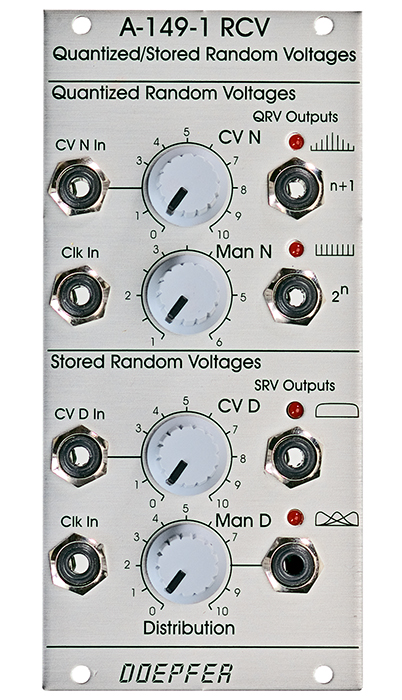
The "Quantized Random Voltages" section has available 2 CV outputs: "N+1 states" and "2N states". N is an integer number in the range 1...6 that can be adjusted with the manual control (Man N) and an external control voltage CVN with attenuator. Whenever the rising edge of the input clock signal (Clk In) appears a new random voltage is generated at the N+1 resp. 2N output. The N+1 output is capable to generate N+1 different voltage levels (or states), the 2N output up to 2N different states. If for example N is set to 4 the N+1 output generates up to 5, the 2N output 16 different states. The voltage steps of the 2N output are adjusted to 1/12 V in the factory. Consequently exact semitones can be obtained in combination with a VCO. The voltage steps of the n+1 output are adjusted to 1.0 V in the factory corresponding to octave intervals in combination with a VCO. For each output a trimming potentiometer is available on the pc board that enables the user to select other voltage steps for the output in question.
Even the "Stored Random Voltages" section has 2 stepped CV outputs available: one with even voltage distribution of the max. 256 output states and second one with adjustable voltage distribution probability. The distribution probability is adjusted by a manual control (Man D) and an external control voltage CVD with attenuator. With the control set fully counterclockwise most of the random voltages will be low magnitude but even medium and high magnitude voltages may appear but with smaller probability. As the control is turned to the right (or a positive control voltage appears at the CVD input) the distribution moves through medium to high magnitude voltage probability. The symbol at the lower jack socket shows this coherence graphically.
The voltage range is 0...+5V for both outputs of the "Stored Random Voltages" section. For each output a trimming potentiometer is available on the pc board that enables the user to select another voltage range for the output in question.
The A-149-1 can be extended by 8 random digital voltages with the A-149-2 Digital Random Voltages module.
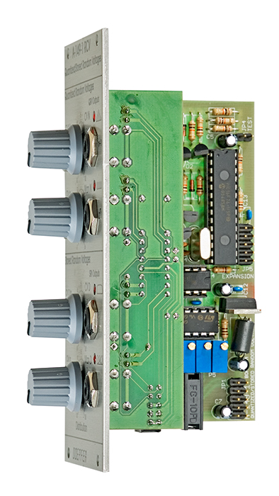
Technical details: If you are interested in technical details here is some information. All random voltages are derived from digital pseudo random generators that work with shift registers and digital feedback via exor gates. The digital output voltages of the shift registers are added up with resistors to obtain variable stepped analog voltages. For the N+1 output all resistors have the same value, the 2N output uses resistors in ratios of 1:2:4:8:16:32. Consequently the N+1 output has less different states available than the 2N output. In addition the digital shift register outputs are gated dependent on the current N voltage (sum of manual control + external CV) by which the number of possible states can be reduced. In contrast to the A-117 the shift registers are not clocked by an internal oscillator but by the external clock input Clk In. The generation of the "Stored Random Voltages" is similar but with different resistor values and more shift register outputs. In addition the random voltage is processed by a non-linear clipping unit with adjustable offset that allows to modify the distribution probability of the voltage levels appearing at the lower output. Even though the module is intended to generate slowly varying control voltages clock frequencies up to moderate audio range (about 2 kHz) can be processed.
User Manuals
Reviews
MP3 examples for A-149-1
Audio-Dateien: A-149 01, A-149 02, A-149 03, A-149 04
Modules used:
- 1 x A-145
- 1 x A-110
- 1 x A-122 (oder anderer Filter / or any other filter)
- 1 x A-149
Patch:
- A-149-1 QRV1 -> Frequency A-110
- A-149-1 QRV2 -> Frequency A-122
- A-145 Rectangle Out -> A-149-1 QRV Clock In
- A-145 Triangle Out -> Pulsewidth A-110
- A-110 Rectangle Out -> A-122 Audio In
- A-122 Audio Out = MP3 Audio
Audio A-149_05
Modules used:
- 1 x A-145
- 1 x A-110
- 1 x A-122 (or any other filter)
- 1 x A-149
- 1 x A-140
Patch:
- A-149-1 QRV1 -> Frequency A-110
- A-149-1 QRV2 -> Frequency A-122 (1)
- A-145 Rectangle Out -> A-149-1 QRV Clock In + A-140 Gate In
- A-145 Triangle Out -> Pulsewidth A-110
- A-140 ADSR Out -> Frequency A-122 (2)
- A-110 Rectangle Out -> A-122 Audio In
- A-122 Audio Out = MP3 Audio
Audio A-149_06
Modules used:
- 1 x A-145
- 1 x A-110
- 1 x A-149
Patch:
- A-145 Sine Out -> A-149-1 QRV Clock In
- A-145 Saw Out -> A-149-1 CV N In
- A-145 Rectangle Out -> A-110 Sync In
- A-149-1 QRV1 -> Pulsewidth A-110
- A-149-1 QRV2 -> Frequency A-110
- A-145 Sine Out -> A-149-1 QRV Clock In
- A-145 Triangle Out -> Pulsewidth A-110
- A-140 ADSR Out -> Frequency A-122 (2)
- A-110 Rectangle Out -> A-122 Audio In
- A-122 Audio Out = MP3 Audio
Audio A-149_07
In A-149_07.mp3 and A-149_08.mp3, the VCO output is also routed through an A-122 whose filter frequency and resonance are controlled by an A-140. In this case too, the VCO Sync input simulates an early reflection. As in the other examples, the A-149's ADSR trigger and clock come from the A-145 LFO.
No additional effects used !