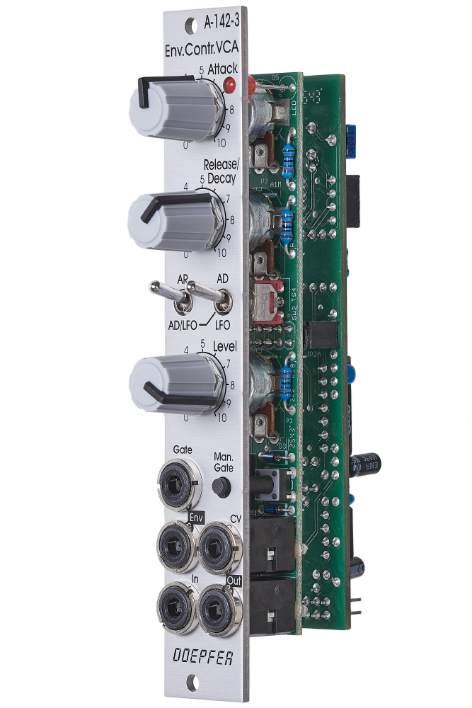
Das Modul A-142-3 beinhaltet einen VCA, der von einer AR/AD-Hüllkurve gesteuert wird, die auch als LFO arbeiten kann.
Module A-142-3 contains an envelope controlled VCA behind a front panel with 4 HP only. It is the combination of a VCA and a AD/AR envelope generator, that can work also as an LFO. The envelope generator has exponential curve shapes (charge/discharge curves of a capacitor). The VCA has a linear control scale.
Applications:
Virtually in each patch one or more envelope/VCA combos together with a sound source are very useful, mainly for percussive sounds
Additional technical information:
- range of the Attack and Decay/Release time: about 4 ms ... 7 s or about 0.1ms ... 150 ms, according to the jumper setting
- frequencies in LFO mode: about 100 Hz ... 0,05 Hz (i.e. 20 s period) or about 2.5kHz ... 2Hz, according to the jumper setting
- an internal jumper can be used to select one of two time ranges. With installed jumper the time range for attach and release/decay is about 4 ms ... 7 s, without jumper about 0.1ms ... 150 ms
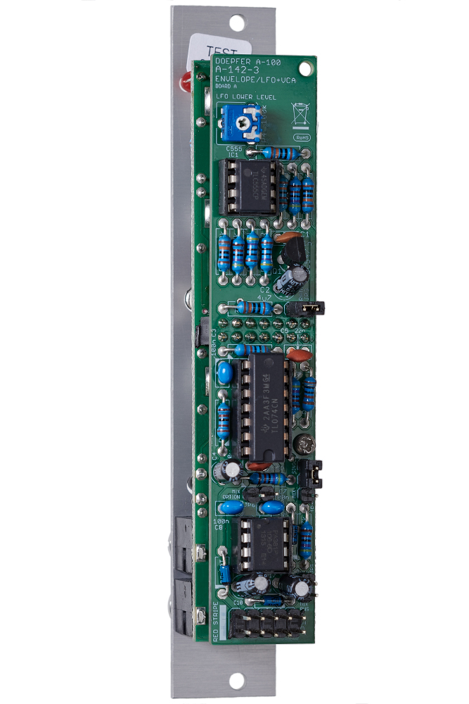
- a trimming potentiometer is used to adjust the level that defines the transition of the falling into the rising slope in LFO mode. This canges also the frequency ranges because the lenght of the falling slope affects the frequency
- the voltage level of the used gate signal has to be at least +5V and the rising/falling slopes has to be fast enough. Otherwise the envelope will be not work in the right way. We discovered that some modules from other manufacturers do not meet these specifications. In this case the level shifter module A-183-4 may help by connecting one unit of the the module between the gate source and the gate input of the A-142-2.
- the VCA (CEM3381) is suitable only for audio signals (AC coupled), it is not suitable for the processing auf control voltages
- the envelope generator has exponential curve shapes (charge/discharge curves of a capacitor)
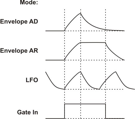
- also in LFO mode the curve shapes are exponential (see sketch)
- when a gate signals is applied in LFO mode the gate controlled envelope and the LFO signals interfere with each other
- the output voltage range of the envelope/LFO is about 0 - 10V (10V = attack peak), the LFO signal is not zero symmetrical !
- the envelope output is attenuated by about 50% (i.e. 0...+10V -> 0...+5V) and normalled to the VCA CV input socket
- the control voltage range of the VCA CV input is about 0...+5V when an external control voltage is used to control the VCA
- the VCA has a linear control scale
- the manual Gate button can also be used to "mute" the external Gate signal, i.e. the external Gate signal is ineffective while the Gate button is operated
- the module is not half an A-142-2 ! The envelope/LFO and the VCA circuits are completely different compared to the A-142-2. Envelope and LFO are based on the timer circuit 555, for the VCA the CEM3381 is used
- Changing the positions of the jumpers allows to modify the factory settings. The following document shows the positions and functions of the jumpers of the module: A142_3_trimming_potentiometers_and_jumpers.pdf
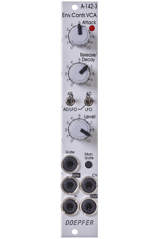
- LED control (envelope/LFO display)
- Attack (A), manual control
- Decay/Release (D/R), manual control
- Mode switches:
- AD (attack-decay envelope) - AR (attack-release envelope)
- Envelope or LFO (LFO only when left switch is in position "AD/LFO")
- Level: manual audio level control (audio input of the VCA)
- Gate Input (min. +5V, max. +12V)
- Manual Gate (momentary switch)
- Env: envelope/LFO output (about 0...+10V)
- CV: VCA control voltage input, voltage range 0...+5V, normalled to the envelope output via 50% attenuator
- In: audio input
- Out: audio output