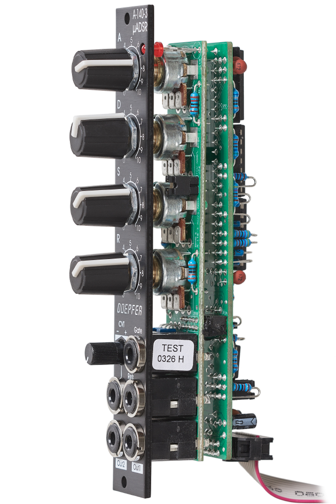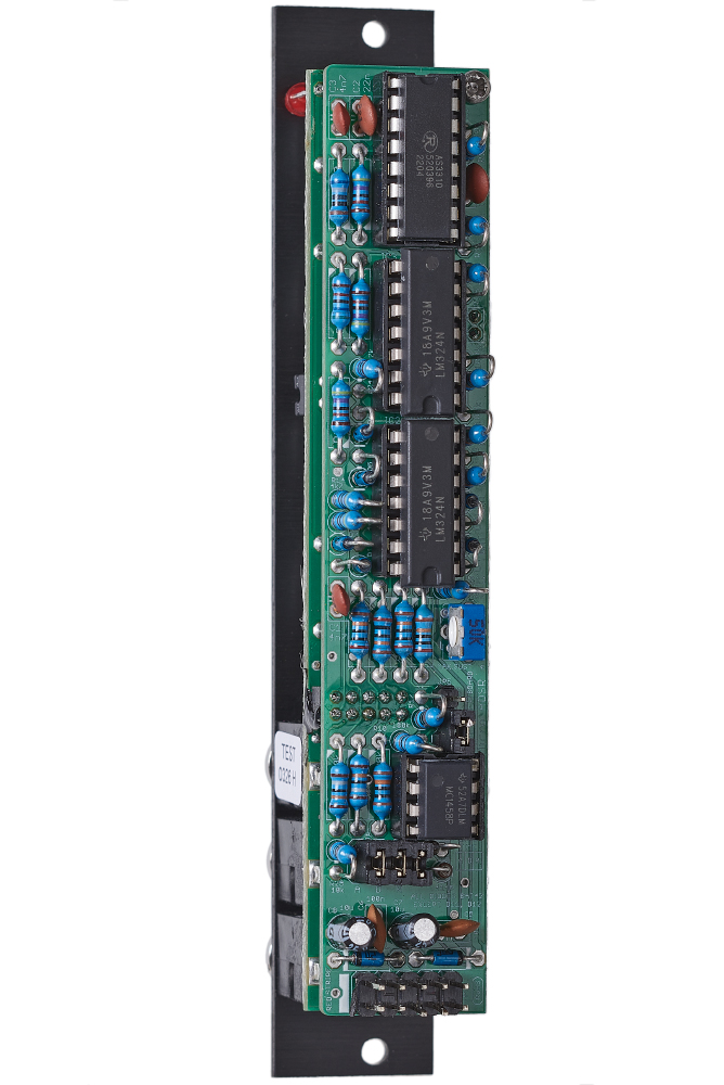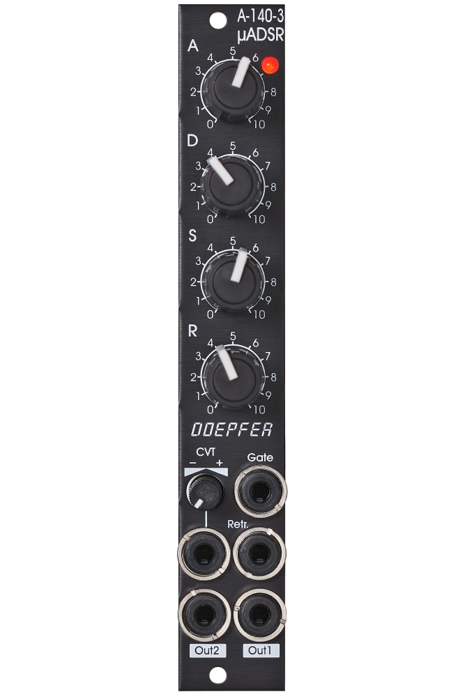
Module A-140-3 is the single version of module A-140-2. It contains an ADSR type voltage controlled envelope generators with exponential curve shapes (charge/discharge curves of a capacitor) with voltage control for the envelope parameters.
The basic functions of an ADSR envelope is described in the user's manual of module A-140.
The voltage control of envelope parameters is mentioned in the user's manual of module A-141.
But the A-140-3 has only one control voltage input CVT with attenuator available and one has to decide via the jumpers which parameters are controlled by CVT and into which direction.
The output voltage range for the envelope is about 0 - 10V (10V = attack peak). The time range of Attack/Decay/Release is about 1ms to 30s.
By means of internal jumpers one can select which time parameters are controlled by the CVT input (e.g. D only or D+R or A+D+R). Socket CVT can be normalled to an internal fixed voltage (i.e. the switching contact is then connected to an internal fixed voltage). That way it's possible to change e.g. all time parameters simultaneously by means of the CVT control.
Another jumper is used to set output 2 to normal or inverted envelope.
In the factory CVT is assigned to all time parameters (A,D,R) zugeordnet, socket CVT is normalled to a fixed voltage and output 2 is not inverted.
Changing the positions of the mentioned jumpers allows to modify the factory settings. The following document shows the positions and functions of the jumpers of the module: A140_3_trimming_potentiometers_and_jumpers.pdf
Additional technical information:
- The voltage level of the used gate signal has to be at least +5V and the rising/falling slopes has to be fast enough. Otherwise the envelope will not work in the right way. We discovered that some modules from other manufacturers do not meet these specifications. In this case the level shifter module A-183-4 may help by connecting one unit of the the module between the gate source and the gate input of the A-140-2.
- A: manual Attack control
- D: manual Decay control
- S: manual Sustain control
- R: manual Release control
- LED (displays the envelope output)
- Gate Input (min. gate level: +5V, max. gate level: +12V)
- Retrigger Input (min. retrigger level: +5V, max. retrigger level: +12V)
- CVT Input with attenuator (CVT = CV Time)
- Envelope Output 1 (normal envelope output)
- Envelope Output 2 (selectable between normal and inverted envelope by means of an internal jumper)